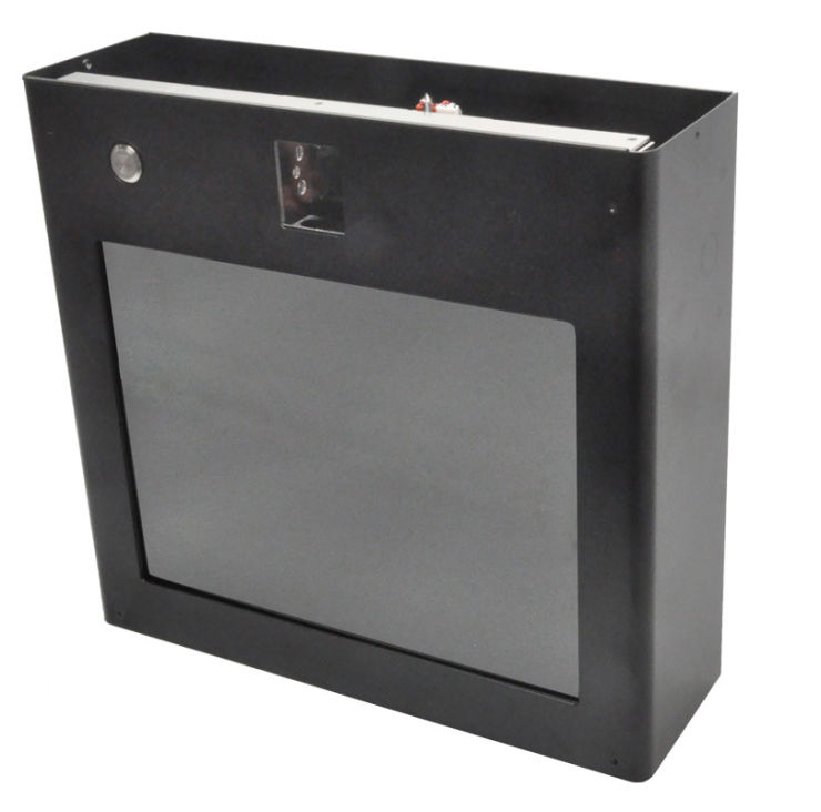
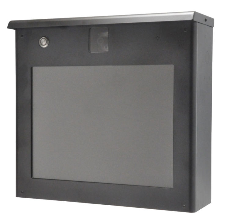
How to Install Series 1500 Customer StationsThese customer stations, or lane stations, have 2-way audio and video capability for use indoors or out. The three models differ in screen size: 7 inches for the Model 1526, 10.4 inches for the Model 1527, and 15 inches for the Model 1529 (measured diagonally). They are housed in durable, powder-coated, steel enclosures. They require only 12 volt DC power from the included 5 amp power supply, and a Cat 5 cable connection to a 1500 Series hub or counter station.
Browse all Customer Stations.
|
|
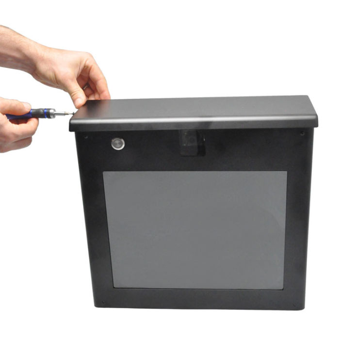
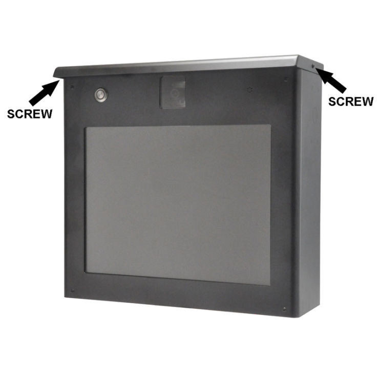
Step 1: Remove the screws that hold the cap (one screw on each side).
|
|
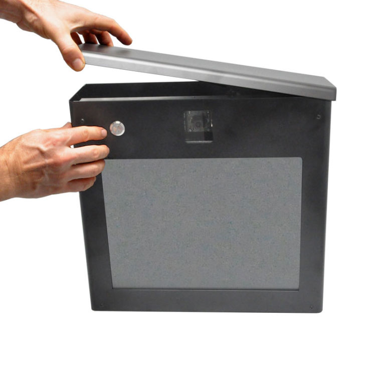
Step 2: Remove the cap.
|
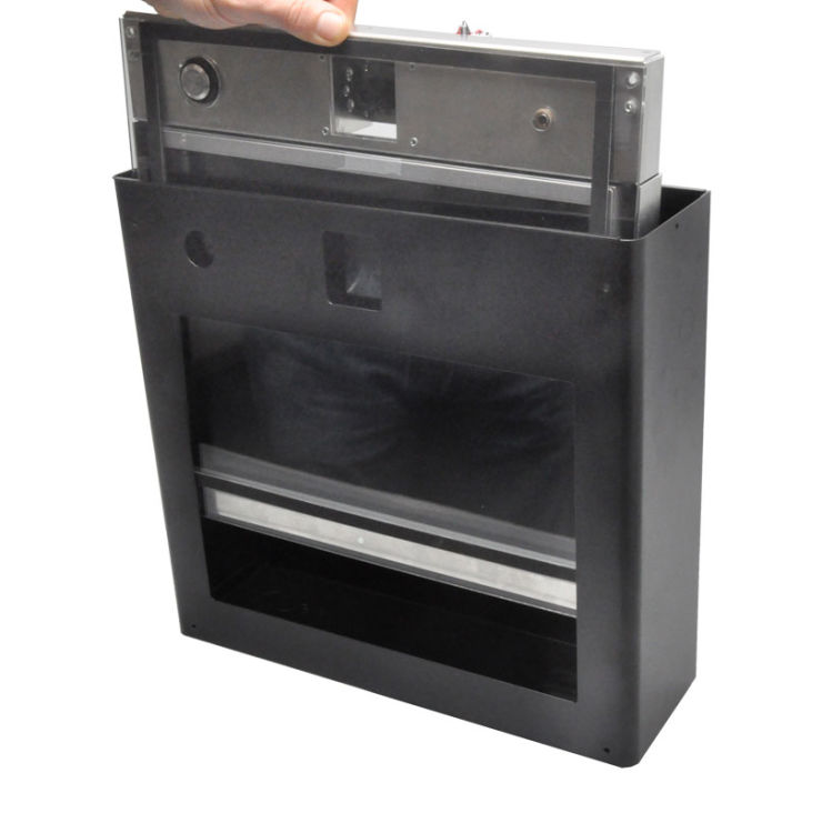
Step 3: Remove the four interior chassis assembly screws from the enclosure.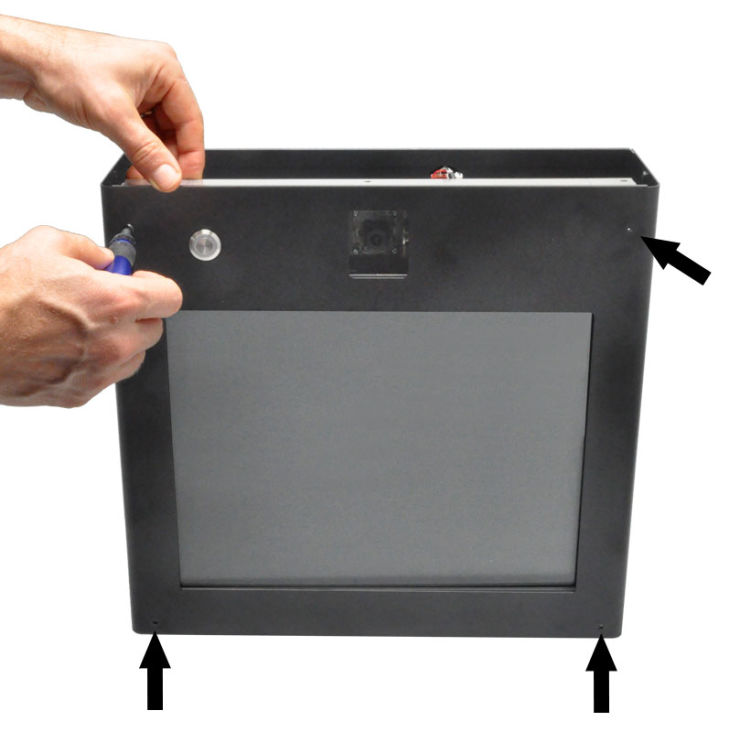
|
Step 4: Remove the interior chassis assembly from the enclosure (four screws on front). Remove the window and set it in a place where it will not get scratched.
|
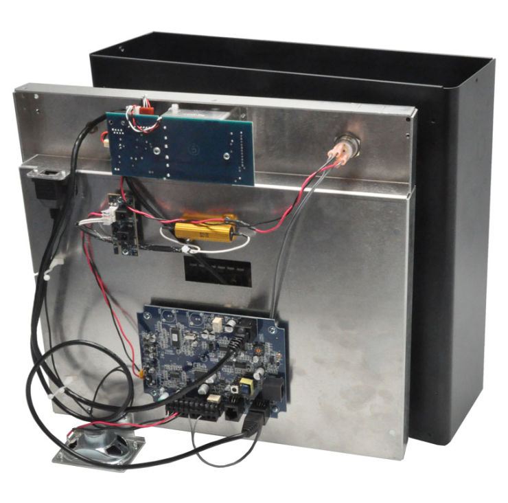
Step 5: With the 1529 case empty, install Model 1546 Handset Add-on if handset operation is desired, or Model 1594 Mounting Arm to support the customer station from an adjacent surface, such as the side of a pneumatic tube unit.
|
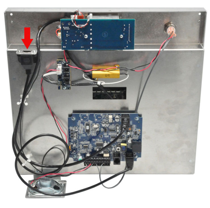
Step 6: The customer station can be mounted directly to a flat surface by removing the appropriate knockouts from the back and screwing it to an electrical box or other surface using the supplied screws. Put the included self-sealing bushing in the wire knockout if the back will be exposed to rain. Puncture the self-sealing bushing to insert the wires. Insert the hub cable through the bushing then terminate the Category 5, 5e, or 6 hub cable with an RJ45 connector and plug it into the Hub port of the customer station chassis assembly.
|
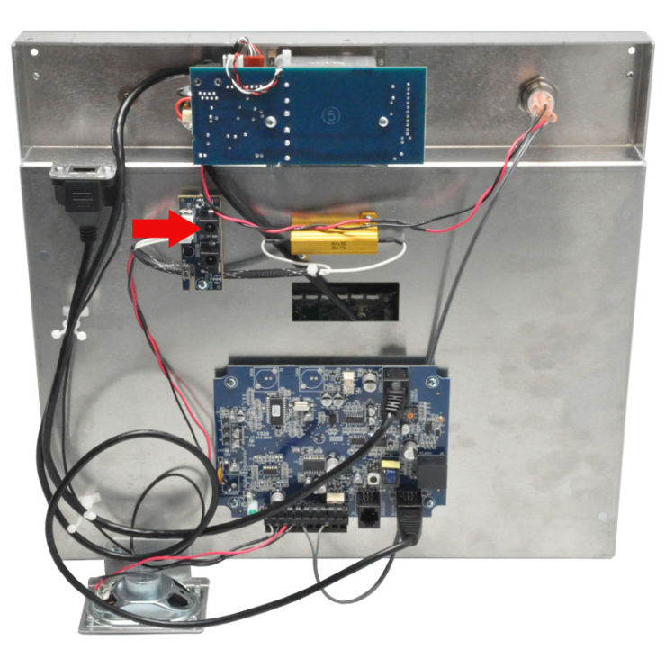
Step 7: Plug the 12-volt power supply into the vacant Power jack on the internal chassis assembly.
|
Step 8: Fit the window onto the chassis assembly before sliding them back into the housing. Note: For best weather gasket performance, evenly tighten the 4 chassis screws until snug.
|
Step 9: Apply power to the customer station and 1500 Series system. Test audio, video and call button performance and adjust settings using the Model 1550A Setup Tool as needed.
 |
Step 11: Reinstall the cap using two screws.
|